| In-System Programming ← | ↑ ScratchMonkey | → High Voltage Serial Programming |
If your MCU has its fuse settings scrambled to an extent that ISP is no longer available to reprogram it, you have to resort to an alternative programming method: High Voltage Programming.
Depending on the MCU you have, you have to use High Voltage Serial Programming (for 8 and 14 pin ICs) or High Voltage Parallel Programming (for ICs with 20 pins or more). Connections for these methods are discussed in their respective sections, but both methods need a high voltage signal, controlled by the Slave Reset pin HVRESET (shown as ⚡️RESET⚡️ in the connection diagrams), for which you need a bit of external hardware.
As their name implies, the High Voltage Serial and High Voltage Parallel Programming techniques require a +12V signal. It should be noted that the current drawn from this signal is quite small.
Here are some ways to generate that 12V signal, depending on what components you have at hand.
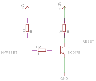
By far the simplest method is to use an external 12V power supply. Either bring the power directly to the bread board (connecting the ground to the Arduino ground), or plug it into the Arduino and use the Arduino Vin pin as the 12V source. To switch this signal on and off using the Slave Reset pin HVRESET, any NPN transistor with a reasonably large hFE should work in this circuit.
R3 is a pull-up resistor ensuring that the 12V signal is turned off when HVRESET is disconnected (e.g. because the sketch is not running), while R1 limits the current flowing through the transistor.
A drawback of this circuit is that the RESET voltage drops as soon as a significant amount of current is drawn. This is not a problem in most programming situations, but can lead to problems if the RESET pin of the target MCU is programmed as an output.
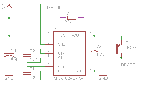
The Maxim MAX662ACPA+ is an integrated circuit that, combined with some capacitors, can generate a 12V, 30mA signal from a 5V input (The same functionality is also available from STMicrolelectronics under the name ST662ACD-TR). The Slave Reset pin HVRESET is here connected to the SHDN pin, which will put the MAX662ACPA+ into shutdown mode.
Since in shutdown mode, the output of the MAX662ACPA+ is 5V instead of 0V, it is preferable to add a transistor as in the previous section to ensure that RESET is indeed 0V. In the circuit shown here, the PNP transistor will only conduct if the emitter is higher than 5V.
Experimentally, omitting the transistor works on all MCUs tested except the ATtiny861 and the ATtiny1634, so if you don't plan on targeting these, you may get away with omitting the transistor.
| In-System Programming ← | ↑ ScratchMonkey | → High Voltage Serial Programming |